Quality & Acceptance
Equipment quality grading, acceptance testing procedures, performance verification protocols, and quality assurance documentation requirements for smart campus environmental monitoring systems.
10.1 Equipment Quality Grading
Environmental monitoring equipment spans a wide range of quality grades, from low-cost indicative sensors to reference-grade analytical instruments. Selecting the appropriate quality grade for each application is critical — over-specifying wastes budget, while under-specifying produces data that cannot meet compliance requirements. The quality comparison image below illustrates the key differences between standard-grade and industrial-grade equipment in a real deployment context, highlighting the differences in accuracy, protection rating, material quality, and calibration requirements.
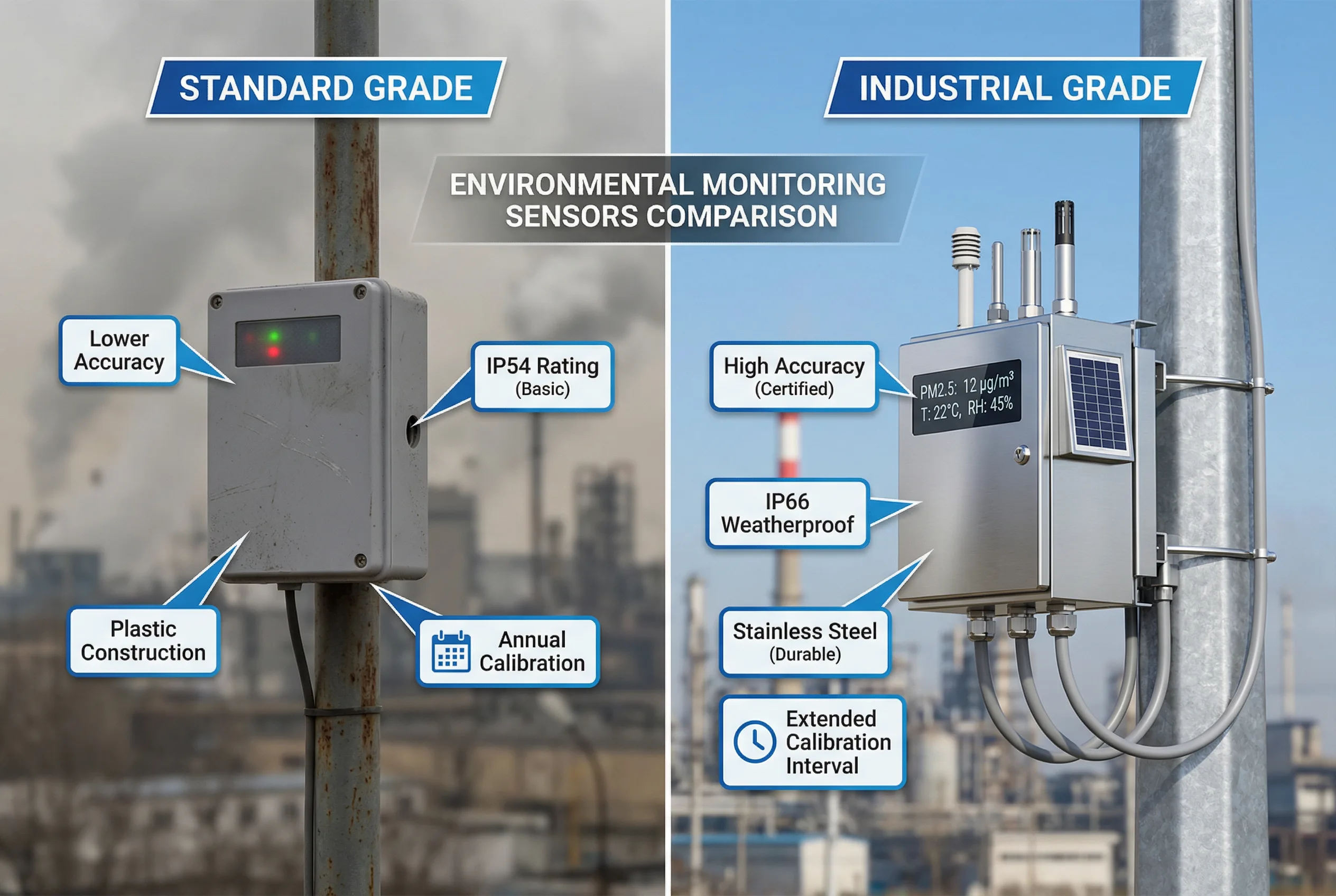
Figure 10.1: Quality Comparison — Standard Grade vs. Industrial Grade Environmental Monitoring Sensors in Real Deployment
The quality grading framework classifies monitoring equipment into four tiers based on measurement uncertainty, environmental protection, material durability, and compliance suitability. The table below summarizes the key characteristics of each tier and provides guidance on appropriate application scenarios.
| Quality Tier | Accuracy | IP Rating | Material | Calibration Interval | Compliance Suitability | Typical Application |
|---|---|---|---|---|---|---|
| Tier 1 — Indicative | ±20–30% | IP44 | ABS plastic | Annual | Not suitable | Indoor comfort monitoring |
| Tier 2 — Standard | ±10–15% | IP54 | Polycarbonate | 6–12 months | Internal reporting only | General outdoor monitoring |
| Tier 3 — Industrial | ±5–10% | IP65–IP66 | Stainless steel / aluminum | 3–6 months | Regulatory reporting (most) | Boundary, compliance monitoring |
| Tier 4 — Reference | ±1–3% | IP67+ | Stainless steel | Monthly to quarterly | All regulatory applications | Reference stations, legal evidence |
10.2 Factory Acceptance Testing (FAT)
Factory Acceptance Testing is conducted at the manufacturer's facility before equipment is shipped to site. The FAT verifies that the equipment meets the specified performance requirements under controlled laboratory conditions. FAT results are documented in a FAT report that is signed by both the manufacturer and the client representative. Equipment that fails FAT must be corrected and re-tested before shipment.
| Test | Method | Acceptance Criterion | Documentation |
|---|---|---|---|
| Accuracy verification | Comparison against NIST-traceable reference standard at 3 concentration levels | Within specified accuracy class (±5% for Tier 3) | Calibration certificate with traceability chain |
| Linearity | 5-point calibration curve across full measurement range | R² ≥ 0.999; residuals within ±2% of full scale | Linearity test report |
| Zero and span stability | 24-hour continuous measurement at zero and span concentration | Drift <1% of full scale per 24 hours | Stability test chart |
| Response time | Step change from zero to 90% of span concentration | T90 within specified value (typically ≤60s) | Response time test record |
| Environmental simulation | Temperature cycling: -20°C to +60°C; humidity 10–95% RH | Accuracy maintained within specification throughout range | Environmental test report |
| Communication protocol | Functional test of all specified protocols (RS485, Modbus, MQTT) | All registers read correctly; no communication errors | Protocol test checklist |
| Power supply range | Test at 85% and 110% of nominal voltage | Normal operation throughout voltage range | Power test record |
10.3 Site Acceptance Testing (SAT)
Site Acceptance Testing is conducted after installation and commissioning to verify that the complete system — including sensors, gateways, network, and software — performs correctly in the actual deployment environment. SAT is more comprehensive than FAT because it tests the integrated system rather than individual components. SAT must be completed and signed off before the system is handed over to the client for operational use.
| SAT Test Item | Test Procedure | Acceptance Criterion | Pass / Fail |
|---|---|---|---|
| Sensor installation verification | Visual inspection of all sensor locations against design drawings | All sensors at specified locations and heights; no obstructions | ☐ Pass ☐ Fail |
| Communication verification | Verify all sensors reporting to platform; check data completeness | 100% of sensors online; no data gaps in 24-hour test period | ☐ Pass ☐ Fail |
| Calibration verification | Field verification using portable reference instrument | Readings within ±10% of reference (or per specification) | ☐ Pass ☐ Fail |
| Alarm function test | Simulate threshold exceedance; verify alarm delivery to all configured recipients | Alarm received within specified response time; all recipients notified | ☐ Pass ☐ Fail |
| Data integrity test | Disconnect network for 2 hours; verify data recovery after reconnection | All data during outage recovered; no data loss; QA flags correct | ☐ Pass ☐ Fail |
| Report generation test | Generate all required report types (hourly, daily, compliance) | Reports generated correctly; data matches platform values | ☐ Pass ☐ Fail |
| User access test | Verify all user accounts with correct permissions | Each user can access only their permitted functions and data | ☐ Pass ☐ Fail |
| Power failure test | Disconnect mains power; verify UPS operation and data continuity | System continues operating on UPS for specified duration; no data loss | ☐ Pass ☐ Fail |
10.4 Ongoing Performance Verification
Performance verification is not a one-time activity — it must be conducted at regular intervals throughout the operational life of the system to ensure that measurement quality is maintained. The verification schedule must be documented in the O&M plan and tracked through the maintenance management system. Verification results must be recorded and reviewed to identify trends that may indicate developing sensor issues before they result in data quality failures.
| Verification Activity | Frequency | Method | Acceptance Criterion | Action if Failed |
|---|---|---|---|---|
| Zero check | Daily (automated) | Automated zero gas injection (if equipped) | Zero reading within ±2% of full scale | Automatic recalibration; alert if persistent |
| Span check | Weekly (automated) | Automated span gas injection (if equipped) | Span reading within ±5% of certified value | Automatic recalibration; alert if persistent |
| Field verification | Quarterly | Portable reference instrument comparison | Within ±10% of reference | Full recalibration; investigate if systematic |
| Full calibration | Per sensor specification (3–12 months) | Multi-point calibration with NIST-traceable standards | All points within accuracy specification | Sensor replacement if cannot be corrected |
| Data completeness review | Monthly | Platform report: % valid data per sensor per month | ≥95% valid data (or per regulatory requirement) | Investigate and resolve cause; document gaps |
| Sensor health review | Monthly | Review sensor health metrics: signal strength, noise, drift | All metrics within normal range | Preventive maintenance; early replacement if trending |
10.5 Acceptance Documentation Package
The acceptance documentation package provides the permanent record of the system as-built and as-tested. This package is essential for regulatory compliance, insurance, future maintenance, and system modifications. The documentation must be delivered in both electronic and hard-copy formats, and must be updated whenever significant changes are made to the system.
| Document | Content | Format | Retention Period |
|---|---|---|---|
| As-built drawings | Final installation drawings reflecting actual installed configuration | AutoCAD DWG + PDF | Life of system + 10 years |
| FAT reports | Factory test results for all equipment | PDF (signed) | Life of system + 10 years |
| SAT report | Site acceptance test results and sign-off | PDF (signed by both parties) | Life of system + 10 years |
| Calibration certificates | NIST-traceable calibration certificates for all sensors | PDF (original certificates) | Life of sensor + 5 years |
| Equipment manuals | Manufacturer operation and maintenance manuals for all equipment | Life of equipment | |
| Software documentation | Platform configuration, user manuals, API documentation | PDF + electronic | Life of system |
| Training records | Records of operator and maintenance staff training | PDF (signed attendance sheets) | 5 years |
| Warranty certificates | Equipment warranty terms and conditions | PDF (original) | Warranty period + 2 years |