Architecture Design
Detailed system architecture, topology diagrams, cabinet wiring design, and network planning for smart campus environmental monitoring deployments.
4.1 Three-Layer System Architecture
The smart campus environmental monitoring system is organized into three functional layers: the Field Sensor Layer, the Edge Computing Layer, and the Cloud Platform Layer. This separation of concerns ensures that each layer can be designed, deployed, and maintained independently, while the standardized interfaces between layers enable integration of diverse sensor technologies and cloud platforms.
The Field Sensor Layer encompasses all physical measurement devices — noise monitors, particulate sensors, gas analyzers, meteorological instruments, water quality probes, and energy meters. These devices communicate with the Edge Computing Layer using wired protocols (RS485 Modbus RTU, 4–20 mA) or wireless protocols (LoRaWAN, NB-IoT, Wi-Fi). The Edge Computing Layer hosts one or more edge gateways per zone, providing local data buffering, protocol translation, alarm processing, and secure uplink to the cloud. The Cloud Platform Layer provides long-term storage, analytics, visualization, reporting, and API integration with third-party systems.
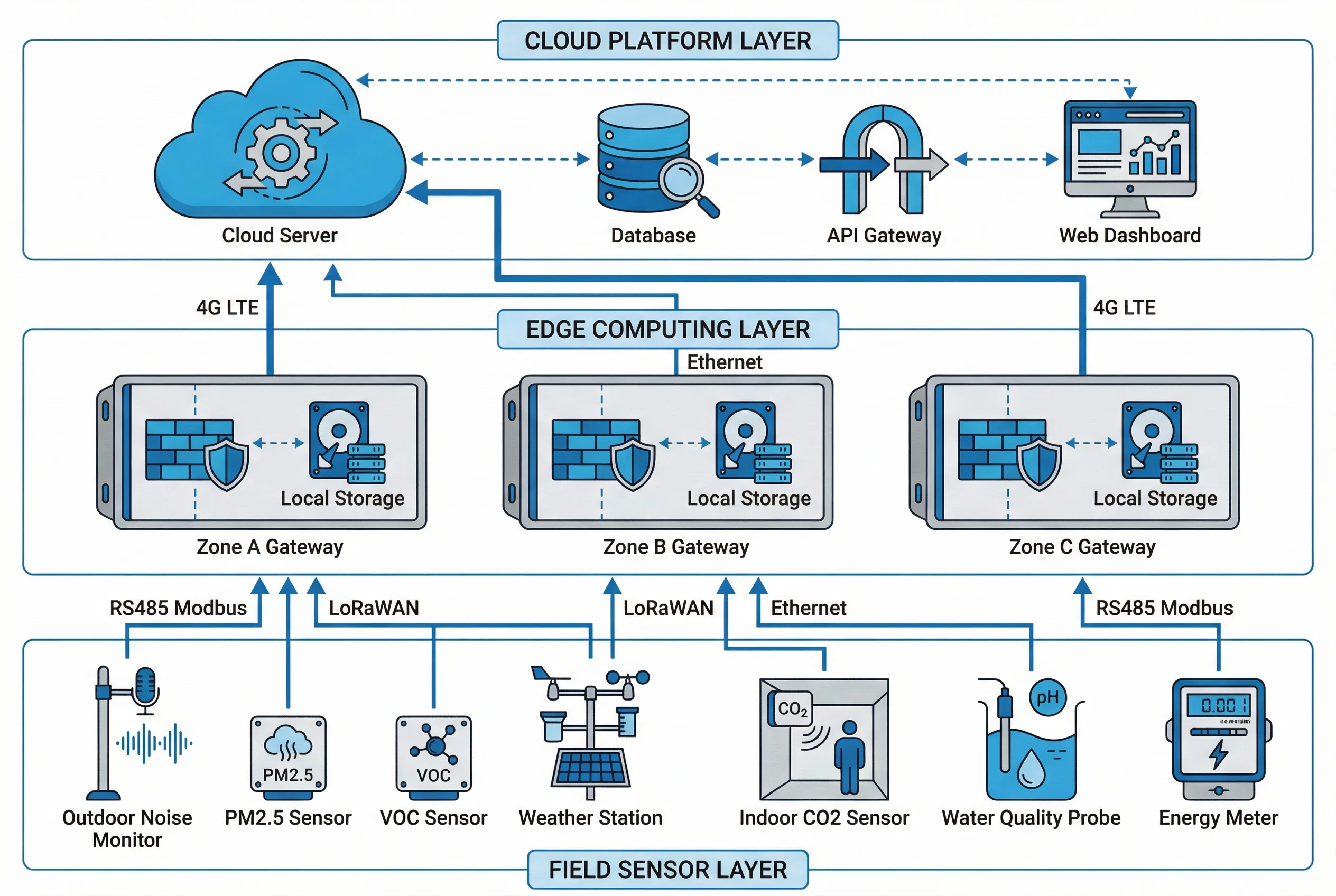
Figure 4.1: Smart Campus Environmental Monitoring System Topology — Three-Layer Architecture with Zone Gateways
| Layer | Primary Function | Key Components | Failure Mode |
|---|---|---|---|
| Field Sensor Layer | Physical measurement and data acquisition | Sensors, probes, meters, mounting hardware | Sensor fouling, power loss, communication fault |
| Edge Computing Layer | Local processing, buffering, alarm, protocol translation | Edge gateways, local storage, relay outputs | Gateway crash, storage full, uplink loss |
| Cloud Platform Layer | Long-term storage, analytics, visualization, API | Database, application server, dashboard, API gateway | Server outage, database corruption, API failure |
4.2 Edge Gateway Zone Design
Each edge gateway serves a defined geographic zone of the campus, typically covering 5–20 sensor nodes depending on the sensor density and communication range. Zone boundaries are drawn to minimize cross-zone cable runs, respect physical barriers (buildings, roads, fences), and align with operational responsibility boundaries (e.g., one zone per building, one zone per boundary section).
The edge gateway must be sized for the number of sensor channels in its zone, with at least 20% spare capacity for future expansion. RS485 bus length must not exceed 1200 m per segment without repeaters, and the maximum number of devices per RS485 bus is 32 (with standard transceivers) or 256 (with enhanced transceivers). LoRaWAN gateway coverage radius is typically 300–1000 m in urban environments depending on building density and interference.
| Parameter | Recommended Value | Notes |
|---|---|---|
| Sensor nodes per gateway | 5–20 nodes | Depends on protocol and data rate |
| RS485 bus length | ≤1200 m per segment | Use repeater for longer runs |
| RS485 devices per bus | ≤32 (standard) / ≤256 (enhanced) | Address conflicts must be avoided |
| LoRaWAN coverage radius | 300–1000 m (urban) | Depends on building density and SF setting |
| Local storage buffer | ≥7 days at 1-min intervals | SSD or industrial SD card; FIFO overwrite |
| Edge CPU utilization | <70% at peak load | Reserve for burst processing and OTA updates |
| Gateway enclosure | IP65 minimum (outdoor); IP20 (indoor cabinet) | Breathable membrane for condensation control |
| Operating temperature | -20°C to +60°C | Verify against local climate extremes |
4.3 Cabinet Wiring Design
The field equipment cabinet is the integration point between the sensor field wiring and the edge gateway. Proper cabinet design ensures safe, reliable, and maintainable operation over the system lifetime. The cabinet must be organized with clear separation between power circuits and signal circuits, proper grounding of all metallic components, and labeled terminal blocks for every connection.
Surge protection devices (SPDs) must be installed on all external connections — power input, RS485 lines, and Ethernet ports — to protect against lightning-induced surges. The SPD must be coordinated with the upstream circuit breaker to ensure that the SPD fails safely without creating a fire hazard. All outdoor cable entries must use waterproof cable glands with appropriate IP rating to prevent water ingress.
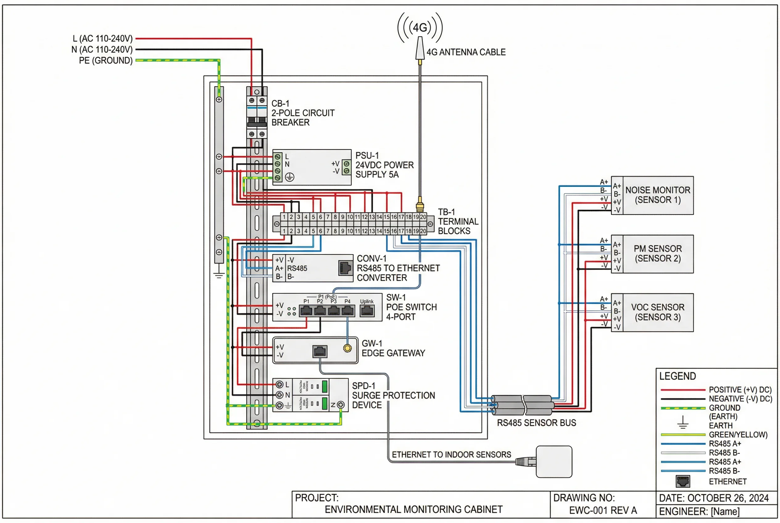
Figure 4.2: Field Equipment Cabinet Wiring Diagram — DIN Rail Layout with RS485, PoE, and 4G Connections
| Component | Specification | Purpose |
|---|---|---|
| Circuit breaker | 2-pole, 6A or 10A, C-curve | Overcurrent protection for cabinet power |
| 24VDC power supply | DIN rail, 24V/5A minimum, CE/UL listed | Power for sensors and gateway |
| Terminal blocks | Spring-cage or screw type, 2.5mm² rated | Organized field wiring termination |
| RS485 converter | RS485 to Ethernet, isolated, DIN rail | Protocol conversion for legacy sensors |
| PoE switch | 4–8 port, industrial, DIN rail, -40 to +75°C | Power and data for PoE sensors |
| Surge protection (AC) | Type 2 SPD, 20kA, coordinated with breaker | Lightning surge protection on AC input |
| Surge protection (RS485) | RS485 SPD, DIN rail, 3kA minimum | Lightning protection on sensor cables |
| Cable glands | IP68, metric thread, appropriate cable OD | Waterproof cable entry |
4.4 Network Planning and Redundancy
Network planning for environmental monitoring systems must address the specific reliability requirements of the application. Safety-critical alarm paths require redundant network paths, while general monitoring data can tolerate brief outages if edge buffering is in place. The network plan must document the primary and backup connectivity for each edge gateway, the expected latency for each path, and the failover behavior when the primary path fails.
For outdoor deployments, cellular (4G LTE or NB-IoT) is the most common primary uplink due to its wide coverage and independence from campus network infrastructure. Fiber Ethernet provides higher bandwidth and lower latency for high-density indoor deployments. Wi-Fi is suitable for indoor sensors in areas with existing Wi-Fi infrastructure but requires careful channel planning to avoid interference.
| Connectivity Type | Bandwidth | Latency | Best Use Case | Redundancy |
|---|---|---|---|---|
| Fiber Ethernet | 100 Mbps – 1 Gbps | <5 ms | High-density indoor, server room | Dual fiber path |
| 4G LTE | 10–100 Mbps | 20–100 ms | Outdoor gateways, remote locations | Dual SIM or fixed line backup |
| NB-IoT | 20–100 kbps | 1–10 s | Low-power sensors, wide area | LoRa fallback |
| LoRaWAN | 0.3–50 kbps | 1–30 s | Battery sensors, construction sites | Multiple gateways |
| Wi-Fi (802.11ac) | 100 Mbps+ | <10 ms | Indoor sensors with existing Wi-Fi | Dual-band roaming |
| RS485 Modbus | 9.6–115.2 kbps | <1 ms | Wired sensors in same cabinet zone | Redundant RS485 bus |
4.5 Typical System Configurations
Three standard system configurations are defined to cover the range of park sizes and complexity levels. Each configuration specifies the number of edge gateways, sensor nodes, connectivity approach, and cloud platform tier. These configurations serve as starting points for project scoping and can be customized based on the specific requirements of each deployment.
| Configuration | Park Size | Edge Gateways | Sensor Nodes | Connectivity | Cloud Tier |
|---|---|---|---|---|---|
| Basic (Pilot) | <5 ha | 1–2 | 5–15 | 4G LTE | Shared SaaS |
| Standard | 5–50 ha | 3–8 | 15–60 | Fiber + 4G | Dedicated SaaS or private |
| Advanced | >50 ha | 8+ | 60+ | Fiber + 4G + LoRa | Private cloud or on-premise |