Installation & Debugging
Step-by-step installation requirements, site preparation guidelines, sensor mounting specifications, cable routing standards, and commissioning and debugging procedures for smart campus environmental monitoring systems.
11.1 Outdoor Installation Requirements
Outdoor sensor installation requires careful attention to mounting height, orientation, cable management, and protection against environmental hazards. The installation must comply with the sensor manufacturer's specifications as well as applicable local regulations and site safety requirements. The outdoor installation scene below illustrates the key requirements for a typical pole-mounted monitoring station, including measurement height, cable routing, power supply, and communication antenna placement.
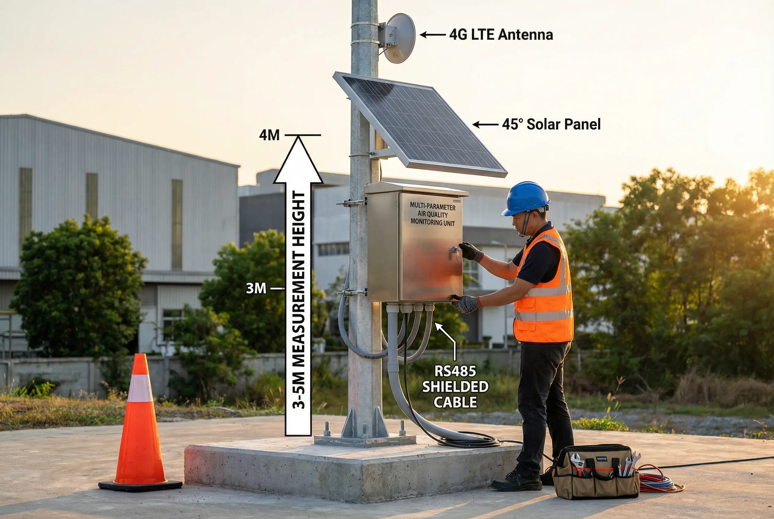
Figure 11.1: Outdoor Installation Requirements — Pole-Mounted Environmental Monitoring Station with Key Installation Specifications
| Installation Parameter | Requirement | Rationale |
|---|---|---|
| Sensor measurement height | 3–5m above ground level (air quality); 1.5m (meteorological) | Avoids ground-level turbulence; representative of breathing zone |
| Minimum distance from obstacles | ≥10× obstacle height (buildings, trees, walls) | Prevents flow distortion and wake effects on measurements |
| Minimum distance from emission sources | ≥50m from major sources (roads, stacks, loading areas) | Avoids near-field contamination; representative ambient measurement |
| Pole foundation depth | ≥1.2m concrete foundation; minimum 400×400mm cross-section | Structural stability for wind loads; prevents frost heave |
| Cable routing | All cables in conduit below 2m height; armored cable or buried conduit for underground runs | Physical protection against damage, vandalism, and UV degradation |
| Solar panel orientation | South-facing (northern hemisphere); 15–45° tilt angle | Maximizes energy harvest; self-cleaning by rain |
| Antenna height | Top of pole; minimum 1m above any metal structure | Maximizes signal strength; avoids multipath interference |
| Grounding | Earth rod ≤10Ω; bonded to pole, cabinet, and SPD | Lightning protection; electrical safety |
11.2 Indoor Installation Requirements
Indoor sensor placement is critical for obtaining representative measurements of the occupied space. Sensors placed too close to HVAC supply vents will measure supply air rather than room air, producing misleadingly low pollutant readings. Sensors placed in corners or near doors will measure localized conditions rather than the average room conditions. The indoor installation scene below illustrates the correct placement of ceiling-mounted and wall-mounted sensors in a typical office environment.
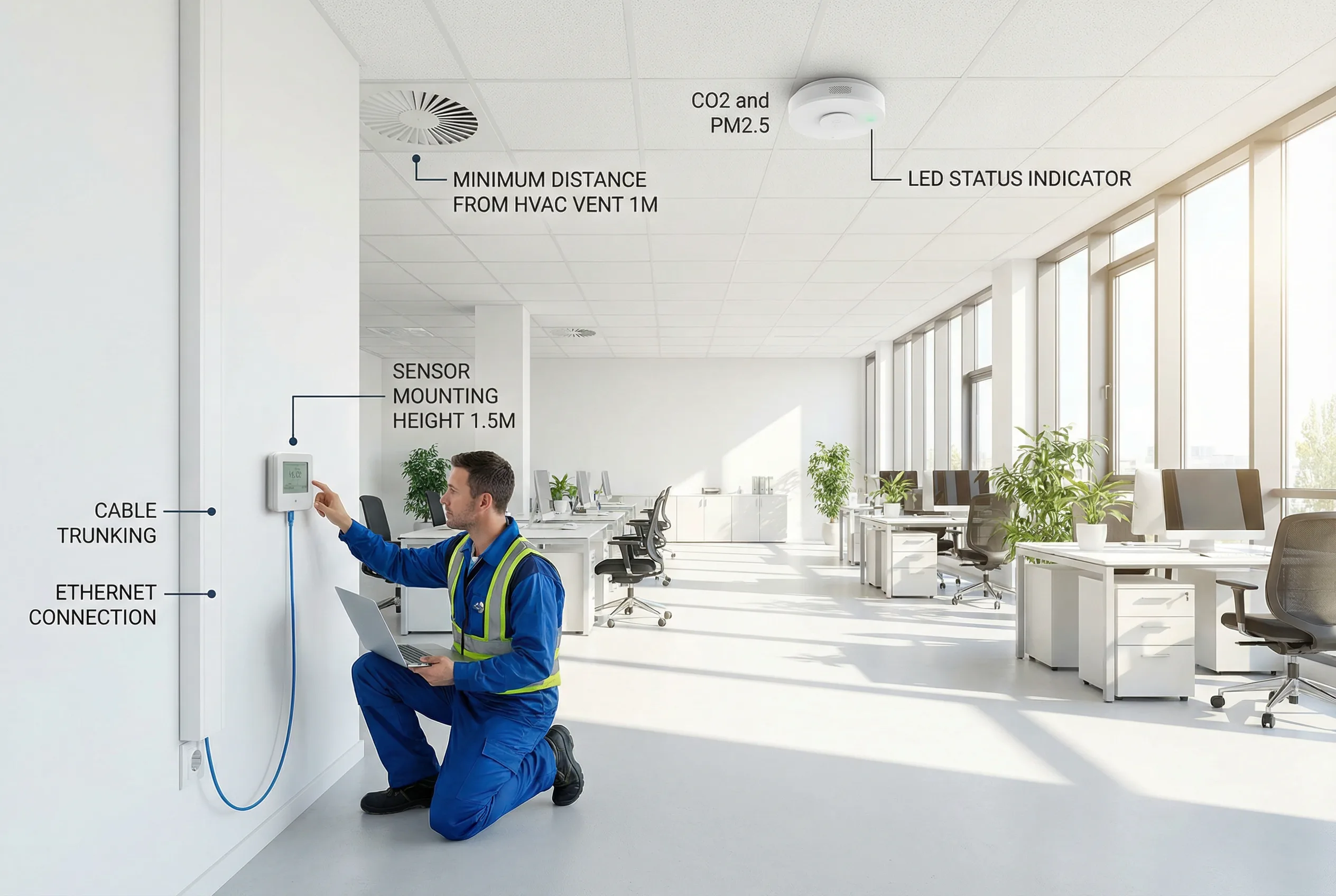
Figure 11.2: Indoor Installation Requirements — Ceiling and Wall-Mounted Sensors in Office Environment with Key Placement Specifications
| Parameter | Wall-Mounted Sensor | Ceiling-Mounted Sensor | Rationale |
|---|---|---|---|
| Mounting height | 1.2–1.8m above floor (breathing zone) | Suspended ceiling or 0.3m below ceiling | Representative of occupant exposure |
| Distance from HVAC supply | ≥1m from supply diffuser | ≥1m from supply diffuser | Avoids dilution effect from supply air |
| Distance from HVAC return | ≥0.5m from return grille | ≥0.5m from return grille | Avoids preferential sampling of return air |
| Distance from windows/doors | ≥1m from exterior openings | ≥1m from exterior openings | Avoids infiltration effects |
| Distance from heat sources | ≥0.5m from computers, printers, lighting | ≥0.5m from heat sources | Avoids thermal plume effects on temperature/humidity |
| Coverage area | 1 sensor per 100–200 m² floor area | 1 sensor per 100–200 m² floor area | Adequate spatial resolution for zone management |
| Cable management | White cable trunking; concealed in wall where possible | Above ceiling tile; cable tray | Aesthetics; protection; maintainability |
11.3 Wiring and Termination Standards
Consistent wiring and termination practices are essential for long-term reliability and ease of maintenance. All wiring must be documented with cable schedules, and all cables must be labeled at both ends. Terminal connections must use ferrules to prevent strand breakage and ensure reliable contact. RS485 bus wiring must follow the daisy-chain topology with proper termination resistors at both ends of the bus to prevent signal reflections.
| Wiring Requirement | Standard | Notes |
|---|---|---|
| RS485 topology | Daisy-chain (bus); no star or T-junctions | Maximum 32 devices per segment; 120Ω termination at both ends |
| RS485 cable type | Shielded twisted pair (STP); 0.5mm² minimum | Shield connected at one end only (gateway end) to prevent ground loops |
| Maximum RS485 run length | 1200m per segment at 9600 baud; shorter at higher baud rates | Use RS485 repeater for longer runs |
| Power cable separation | Minimum 200mm separation from RS485/signal cables | Prevents electromagnetic interference; use separate conduits |
| Cable labeling | Both ends; cable number, source, destination, date | Use heat-shrink or self-laminating labels; match cable schedule |
| Terminal ferrules | All stranded wire ends; correct size for wire cross-section | Prevents strand breakage; ensures reliable terminal contact |
| Connector torque | Per manufacturer specification; use torque screwdriver | Under-torque causes intermittent connection; over-torque damages terminal |
| Cable tray fill | Maximum 40% fill ratio in cable trays | Allows heat dissipation; space for future additions |
11.4 Commissioning and Debugging Procedure
Commissioning is the systematic process of verifying that all installed components function correctly individually and as an integrated system. The commissioning procedure must be followed in sequence — hardware verification before power-on, individual device testing before network integration, and local function testing before cloud platform integration. Deviations from the commissioning sequence can result in damage to equipment or difficulty diagnosing faults.
| Step | Activity | Verification | Tool Required |
|---|---|---|---|
| 1 | Pre-power inspection: verify all connections, cable routing, grounding, and SPD installation | Visual inspection checklist; insulation resistance test | Inspection checklist; megohmmeter |
| 2 | Power-on: apply power to cabinet; verify supply voltages at all distribution points | 24VDC ±5% at all sensor terminals; AC voltage correct | Digital multimeter |
| 3 | Individual sensor test: connect each sensor one at a time; verify communication and reading | Sensor responds to Modbus poll; reading within plausible range | Laptop with RS485 diagnostic software |
| 4 | RS485 bus test: connect all sensors; verify all devices respond without errors | No CRC errors; all device addresses unique; no bus conflicts | RS485 bus analyzer |
| 5 | Gateway configuration: configure data collection, reporting interval, and cloud connection | Gateway connects to cloud; data visible in platform | Laptop with gateway configuration software |
| 6 | Platform verification: verify all sensors appear in platform with correct names and units | All sensors online; readings match local display | Platform web interface |
| 7 | Alarm configuration: set alarm thresholds; test alarm delivery | Alarm received by all configured recipients within response time | Platform web interface; test phone/email |
| 8 | Initial calibration: perform field verification against reference instrument | All sensors within ±10% of reference; adjust if needed | Portable reference instrument; calibration gas |
| 9 | 24-hour soak test: run system continuously for 24 hours; review data completeness | ≥99% data completeness; no unexplained gaps or anomalies | Platform data completeness report |
| 10 | SAT sign-off: complete SAT checklist; obtain client signature | All SAT items passed; documentation complete | SAT checklist; acceptance certificate |
11.5 Common Installation Faults and Remediation
Experience from numerous environmental monitoring deployments has identified a set of recurring installation faults that cause the majority of commissioning failures and early-life reliability issues. Understanding these common faults and their remediation enables installation teams to avoid them proactively and diagnose them quickly when they occur.
| Fault | Symptom | Root Cause | Remediation |
|---|---|---|---|
| RS485 address conflict | Multiple sensors not responding; intermittent communication errors | Two or more sensors configured with same Modbus address | Disconnect all sensors; reconnect one at a time; assign unique addresses |
| Missing termination resistor | Communication errors increase with cable length; errors at high baud rate | No 120Ω terminator at end of RS485 bus | Install 120Ω resistor at both ends of bus; verify with oscilloscope |
| Ground loop on RS485 shield | Noise on RS485 signal; intermittent errors | Shield connected at both ends, creating ground loop | Connect shield at gateway end only; insulate shield at sensor end |
| Sensor in flow shadow | Readings consistently lower than expected; poor correlation with reference | Sensor installed behind obstacle that blocks airflow | Relocate sensor to unobstructed location; verify with smoke test |
| Power supply overload | Sensors intermittently dropping offline; PSU running hot | Total sensor load exceeds PSU rating | Calculate total load; replace PSU with adequate rating; add second PSU |
| Incorrect Modbus register mapping | Readings are wrong value, wrong units, or nonsensical | Register address or data type mismatch in gateway configuration | Verify against sensor Modbus register map; correct gateway configuration |
| Time synchronization failure | Data timestamps incorrect; data gaps appear at wrong times | Gateway NTP synchronization not configured or NTP server unreachable | Configure NTP server; verify network access to NTP; check firewall rules |