Support & Integration
Supporting infrastructure requirements, third-party system integration, BMS/SCADA connectivity, and ecosystem dependencies for smart campus environmental monitoring deployments.
7.1 Supporting Infrastructure Overview
The smart campus environmental monitoring system depends on a range of supporting infrastructure systems that must be planned and provisioned as part of the overall deployment. These supporting systems span six categories: power and protection, network infrastructure, mounting and enclosure, calibration and maintenance tools, alarm and output systems, and data integration interfaces. Failure to adequately plan any of these supporting categories is a common cause of project delays and post-deployment reliability issues.
The integrated supporting equipment diagram below illustrates the complete ecosystem of supporting systems and their relationship to the central monitoring platform. Each category contains multiple components that must be specified, procured, installed, and commissioned as part of the overall system delivery. The diagram serves as a planning checklist to ensure that no supporting system is overlooked during project scoping.
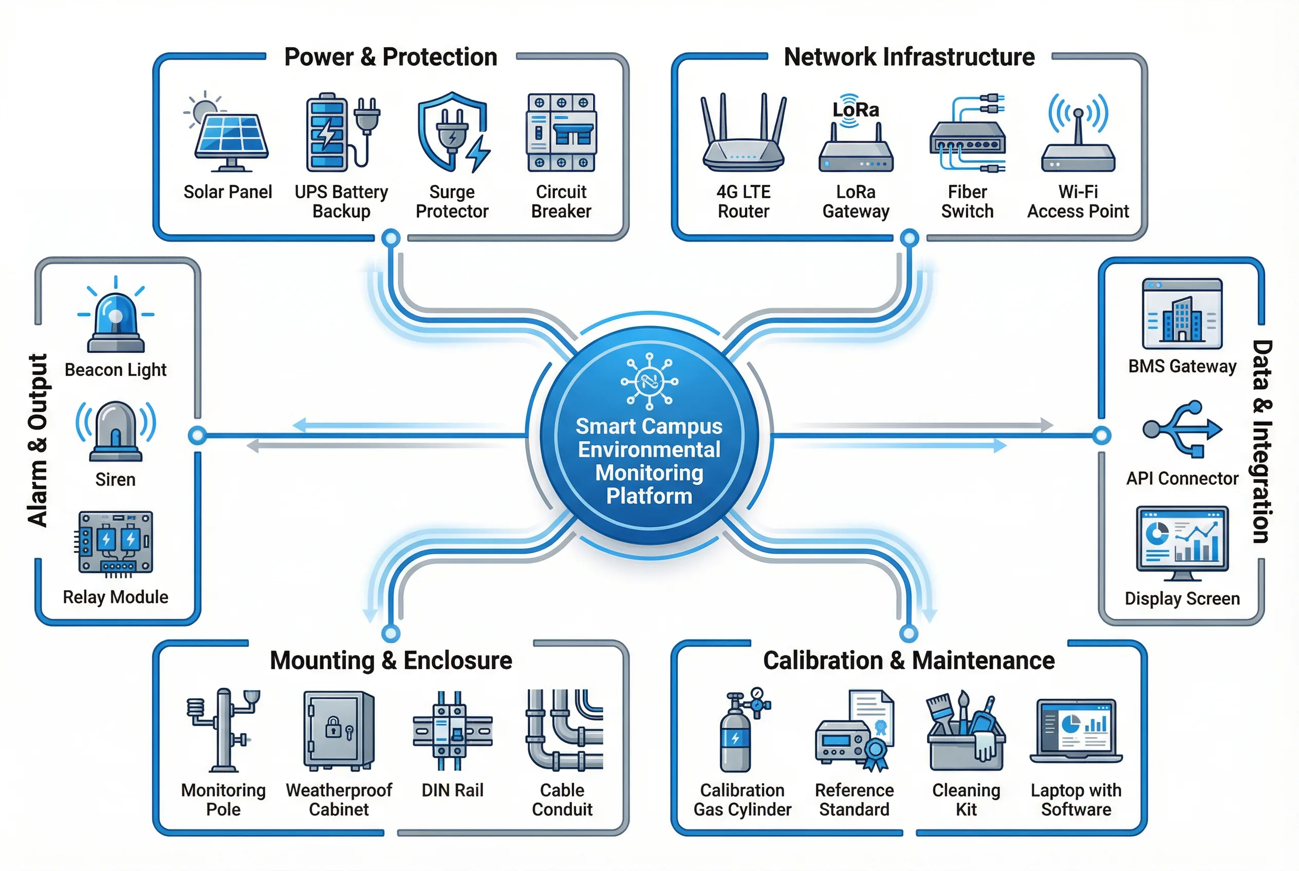
Figure 7.1: Integrated Supporting Equipment Diagram — All Supporting Systems in a Single View
7.2 Power and Protection Requirements
Reliable power supply is the foundation of continuous monitoring. Power interruptions cause data gaps that may be unacceptable for compliance monitoring applications. The power design must address the primary power source, backup power duration, surge protection, and power quality requirements for each monitoring station. Solar-assisted systems require careful battery sizing to ensure adequate backup during extended low-irradiance periods.
| Component | Specification | Purpose | Sizing Guidance |
|---|---|---|---|
| AC mains supply | 220V AC, dedicated circuit, 10A MCB | Primary power for fixed stations | One circuit per cabinet; no shared circuits with other loads |
| 24VDC power supply | DIN rail, 24V/5A minimum, CE/UL | Sensor and gateway power | Size for 150% of connected load; derating for temperature |
| UPS battery backup | Online or line-interactive; 4–8h backup | Continuity during power outage | Calculate load × backup hours; add 20% margin |
| Solar panel + controller | 20–100W panel; MPPT controller; 12V/24V | Remote station primary or backup power | Size for worst-case irradiance month; 3-day battery reserve |
| Surge protection (AC) | Type 2 SPD, 20kA, DIN rail | Lightning surge protection on AC input | Coordinate with upstream MCB; replace after major strike |
| Surge protection (RS485) | RS485 SPD, 3kA minimum, DIN rail | Lightning protection on sensor cables | Install at both ends of long cable runs |
| Earth rod and bonding | Copper-clad steel rod, ≥2.4m; <10Ω resistance | Safety grounding and SPD discharge path | Measure resistance after installation; add rods if needed |
7.3 Network Infrastructure Requirements
The network infrastructure supporting the monitoring system must provide reliable, secure connectivity from field sensors to the cloud platform. Network planning must consider the coverage requirements of each sensor type, the bandwidth requirements of the data streams, the latency requirements of alarm paths, and the redundancy requirements of the overall system. The network design must be documented and reviewed by the IT security team before deployment.
| Infrastructure Component | Specification | Coverage / Capacity | Key Requirement |
|---|---|---|---|
| 4G LTE router/gateway | Industrial grade, dual SIM, -20 to +60°C | Park-wide cellular coverage | Dual SIM for carrier redundancy; VPN support |
| LoRa gateway | 8-channel, outdoor IP65, 4G backhaul | 300–1000m radius per gateway | Antenna height ≥5m; avoid metal obstructions |
| Fiber switch | Industrial managed, DIN rail, SFP ports | Building or zone backbone | VLAN support; SNMP monitoring; redundant power |
| Wi-Fi access point | Wi-Fi 5 or 6, outdoor IP67, PoE powered | 50–100m radius per AP | WPA3 security; separate SSID for sensors |
| NB-IoT module | Cat-NB1/NB2, low power, DIN rail or embedded | National coverage via carrier | PSM/eDRX for battery life; carrier SLA required |
| Network management | SNMP/NetFlow monitoring; centralized NMS | All network devices | Alert on link down; bandwidth utilization monitoring |
7.4 Third-Party System Integration
The environmental monitoring platform must integrate with multiple third-party systems to deliver its full value. Integration with the Building Management System (BMS) enables correlation of environmental data with HVAC operation and energy consumption. Integration with the EHS management system enables automatic population of compliance reports and incident records. Integration with the property management system enables tenant notification and service request generation.
All integrations must use documented, versioned APIs with authentication and rate limiting. Integration points must be tested during commissioning and monitored in production to detect failures. A data dictionary must be maintained to document the field mapping between the monitoring platform and each integrated system, ensuring that data is correctly interpreted by all consumers.
| Integration Target | Protocol / API | Data Exchanged | Integration Priority | Key Requirement |
|---|---|---|---|---|
| Building Management System (BMS) | BACnet/IP, Modbus TCP, REST API | Environmental readings, alarm states, HVAC setpoints | High | Bi-directional; real-time; data dictionary alignment |
| EHS Management System | REST API, SFTP (report files) | Compliance data, alarm events, calibration records | High | Audit trail; data integrity; regulatory format |
| Property Management System | REST API, webhook | Alarm notifications, tenant reports, work orders | Medium | Tenant data isolation; RBAC; notification routing |
| SCADA / DCS | OPC-UA, Modbus TCP | Real-time sensor values, alarm states | Medium | Latency <5s; data quality flags passed through |
| Regulatory reporting portal | XML/CSV upload, REST API | Compliance data in regulatory format | High | Format compliance; digital signature; submission log |
| Energy management system | REST API, Modbus TCP | Energy meter readings, demand data | Medium | Time synchronization; meter accuracy verification |
| GIS / mapping platform | REST API, WMS/WFS | Sensor locations, zone boundaries, plume maps | Low | Coordinate system alignment; real-time update |
7.5 Alarm and Output Integration
Alarm integration ensures that environmental excursions trigger appropriate responses from the relevant stakeholders. The alarm routing matrix defines which alarms are sent to which recipients through which channels, based on the alarm severity, the affected zone, and the time of day. Multi-channel alarm delivery — combining platform notifications, SMS, email, and local beacon — ensures that critical alarms reach the responsible party even when one channel is unavailable.
| Alarm Severity | Response Time Target | Notification Channels | Escalation Path | Documentation |
|---|---|---|---|---|
| Critical (safety) | <60 seconds | Local beacon + siren + SMS + platform push | EHS officer → Site manager → Emergency services | Auto-generated incident record |
| High (compliance) | <5 minutes | Platform push + SMS + email | EHS officer → Compliance manager | Alarm log + evidence package |
| Medium (operational) | <30 minutes | Platform push + email | O&M team → Facility manager | Work order generation |
| Low (informational) | Next business day | Daily digest email | O&M team | Trend report |
| Sensor health | <4 hours | Platform push + email | O&M team | Maintenance ticket |